NEWS TAG
brand
Raised Access Floor Airflow Rate Calculation for Data Centers & Cleanrooms
A raised access floor is a vital component in modern buildings, particularly in data centers and cleanrooms, where efficient ventilation and heat dissipation are important. This guide explores the calculation of airflow rates for raised floors with perforated panels, considering various factors like perforation rates, material, and environmental needs.
1. What is the Raised Floor Airflow Rate?
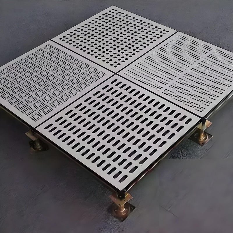
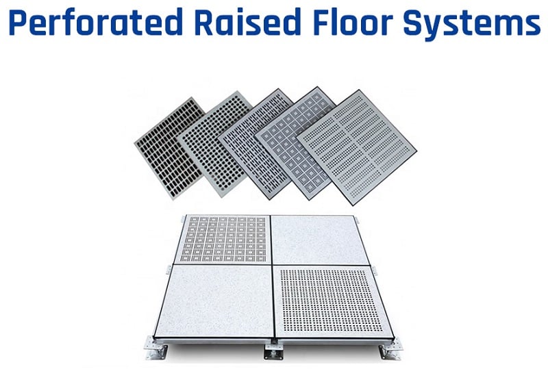
A raised floor is a structural system installed above the ground surface, typically made of wood or metal materials. These floors often incorporate perforations that allow air to circulate, promoting both ventilation and heat dissipation. The raised floor perforation rate is a critical metric, representing the ratio of the perforated area to the total floor area. This rate is essential in evaluating the effectiveness of the floor's ventilation and cooling capabilities.
2. Significance and Influencing Factors of Raised Floor Airflow Rate
The perforation rate directly influences the airflow rate. A higher perforation rate generally means better ventilation and heat dissipation, but at the cost of reduced structural integrity and load-bearing capacity. The following factors affect the perforation rate:
Material: The type of material used impacts both the ventilation and the load-bearing capacity.
Perforation Size and Quantity: Larger or more numerous perforations increase airflow but decrease the structural strength.
The optimal perforation rate for a raised floor depends on the specific requirements of the environment, such as cooling needs and load-bearing demands.
3. How to Optimize Raised Floor Airflow Rate?
To achieve the best performance, the perforation rate must be balanced with the structural and functional needs of the space. If the perforation rate is too low, the ventilation and cooling effects will be insufficient. Conversely, if it is too high, the floor's load-bearing capacity and stability may be compromised.
Optimization Techniques:
Choose an appropriate perforation area and quantity based on airflow needs.
Optimize the layout and distribution of perforations.
Select suitable perforation shapes to enhance airflow while maintaining strength.
Use appropriate materials and installation methods to improve overall durability and performance.
4. General Range of Perforated Floor Airflow Rates
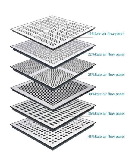
Typically, raised floors have perforation rates between 20% and 30%, which provide a balance between airflow and structural integrity. However, in environments with higher ventilation needs, such as data centers, perforation rates of 50% or more may be required.

Common Perforation Rates:
20% to 30%: General-purpose raised floors, offering good ventilation with adequate load-bearing capacity.
25% or higher: Ideal for environments requiring enhanced cooling, such as large data centers.
50%: Used in extreme cases where maximum ventilation is necessary, but at the cost of reduced floor strength.
These values are general guidelines; actual perforation rates should be determined based on the specific needs and conditions of the site.
5. Factors Affecting Raised Floor Perforation Rates
Several factors must be considered when designing raised floors with perforated panels:
Ventilation Requirements - The cooling needs of the equipment in the room determine the necessary airflow volume.
Load-Bearing Capacity - Higher perforation rates reduce the floor's ability to support heavy equipment.
Sound Insulation - In some environments, noise control is essential, and perforation rates may need to be adjusted to balance airflow with soundproofing.
6. Specific Value Reference for Raised Access Floor Airflow Rates
Here are specific airflow rates for different perforation percentages under a constant pressure difference of 5PA:
17% perforation rate: Surface wind speed of 0.45 m/s, ventilation volume of 583.2 m³/h.
25% perforation rate: Surface wind speed of 0.65 m/s, ventilation volume of 842.4 m³/h.
50% perforation rate: Surface wind speed of 1.25 m/s, ventilation volume of 1,620 m³/h.
These values are useful references when designing or optimizing a raised floor system. For instance, under similar conditions, one 50% perforated panel provides the same ventilation as three 17% panels.

7. Raised Access Floor Airflow Rate for Cleanrooms
In Class 100 cleanrooms, the perforation rate should be between 10% and 15% to maintain cleanliness while ensuring adequate ventilation. Higher rates risk compromising cleanliness by allowing dust and contaminants to enter the environment.
Guidelines for Cleanroom Perforation Rates:
Impact on Cleanliness - A low perforation rate reduces the risk of dust contamination but hinders airflow.
Ventilation and Safety - A moderate rate (10%-15%) balances cleanliness with proper ventilation, ensuring that harmful gases are efficiently removed.
Selection Tips:
For cleanrooms with stricter cleanliness requirements, a perforation rate closer to 10% is advisable.
In cleanrooms with higher ventilation needs, a rate closer to 15% can be used.
8. How to Calculate Raised Floor Airflow Rate for Your Project
Calculating the airflow rate for your raised floor project involves a few key steps and considerations. Here’s a quick guide:
Step 1: Determine the Required Ventilation Volume
The first step is to assess the cooling and ventilation needs of the space. This is typically based on:
The power consumption and heat generation of equipment in the room, such as servers in a data center.
The desired temperature and air quality standards for the environment.
From this, calculate the required airflow volume in cubic meters per hour (m³/h).
Step 2: Select the Appropriate Perforation Rate
Based on the cooling and airflow needs, choose an appropriate perforation rate:
General-purpose environments: Use perforation rates between 20% and 30%.
High ventilation environments: Consider perforation rates of 50% or more.
Cleanrooms: For environments like Class 100 cleanrooms, use perforation rates between 10% and 15%.
Step 3: Calculate the Airflow for Individual Panels
Use the following formula to estimate the airflow for each perforated panel:
Airflow (m³/h)=Surface Wind Speed (m/s)×Panel Area (m²)×3600
For example, if you have a 600×600 mm panel with a 17% perforation rate, at a wind speed of 0.45 m/s, the airflow would be:
0.45m/s×0.36m²×3600=583.2m³/h
Step 4: Adjust Based on Pressure Differences
The airflow rate can vary based on the pressure difference across the floor. A common pressure difference for raised floors is 5PA. Ensure that the design maintains this pressure to achieve the calculated airflow rates.
Step 5: Sum Up the Total Airflow
Multiply the airflow of each panel by the number of panels in the installation to calculate the total airflow for the room. For instance, if you are using 4 panels with a 17% perforation rate, each providing 583.2 m³/h, the total airflow would be:
4×583.2=2332.8m³/h
Step 6: Adjust for Equipment Like FFUs
If the room contains Fan Filter Units (FFUs), account for the airflow they generate. For example, a 1200×600 mm FFU might correspond to two 600×600 mm raised floor panels with a 17.5% perforation rate.
Step 7: Refine Based on CFD Analysis
Use Computational Fluid Dynamics (CFD) simulations to further refine the design. CFD can help predict airflow deviations and optimize the placement and perforation rate of panels to ensure even distribution of airflow throughout the room.
9. Perforation Rate Calculation Example
For a Class 100 cleanroom, we calculate the airflow rate based on a 1200×600 FFU (Fan Filter Unit) with a face wind speed of 0.35 m/s. The wind speed at the return air inlet is generally set to 2 m/s. Using a 600×600 raised floor panel with a 17.5% perforation rate, we find that two raised floor panels correspond to one FFU.
The 17.5% perforation rate is commonly used because it is easy to manufacture and provides a good balance between airflow and structural integrity.
10. Raised Floor Perforated Panel Layout Plan
To optimize airflow, a CFD (Computational Fluid Dynamics) simulation is often conducted to model airflow in the cleanroom or data center.
Steps in Layout Planning:
Request equipment details to obtain accurate airflow conditions.
Model the environment, including room dimensions, return air duct distribution, and equipment placement.
Adjust perforation rates by zone to achieve the desired vertical airflow pattern.
Foresee local airflow deviations and turbulence, and take corrective measures (e.g., use of dampers).
11. Practical Applications and Adjustments
After installation, adjustments may be needed to correct for airflow deviations:
Large Environment Adjustments: Use different perforation rates (e.g., 17%, 25%, 50%) and air regulating valves to fine-tune airflow near return ducts.
Microenvironment Adjustments: Use higher perforation rates (e.g., 25%, 50%) in areas requiring more ventilation, such as near robotic arm equipment or storage areas.
The perforation rate of raised floors is a key factor in determining airflow, heat dissipation, and load-bearing capacity. By carefully selecting and optimizing the perforation rate based on the specific needs of the environment, one can ensure optimal performance in both data centers and cleanrooms. Always consider the material, perforation size, and environmental requirements when designing raised floors for maximum efficiency.

